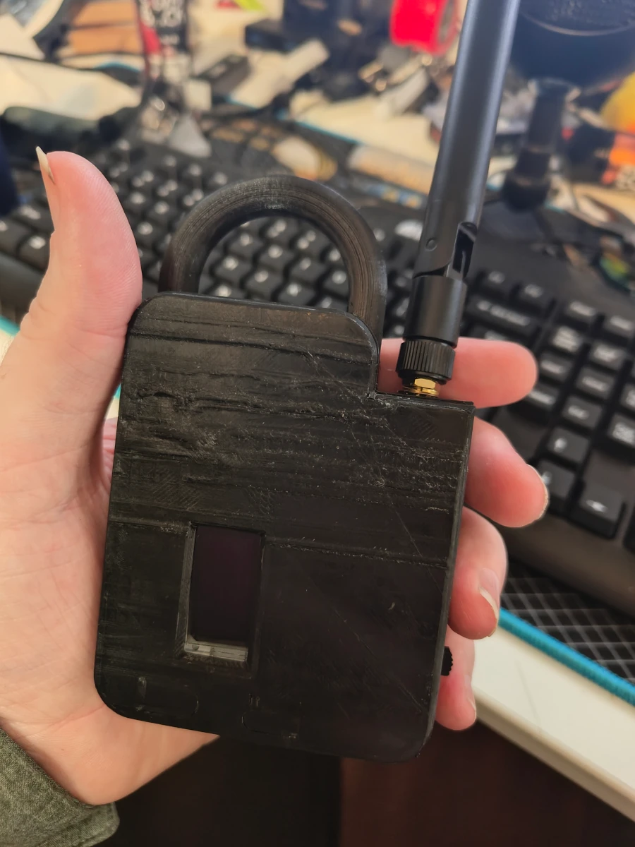
Custom Case for Heltec V3 LoRa Meshtastic
When I picked up my Heltec LoRa radio for Meshtastic, I opted to deck it out with a number of modules it can support, including a large 3Ah battery, full GPS capability, and basic environmental sensors. The base module ships with a basic case which worked for initial testing, but it only held the base module so I needed a 3D printed case to hold everything.
This print is also available on Thingiverse
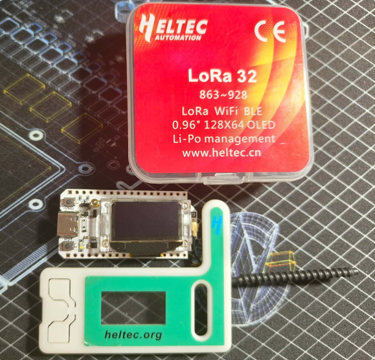
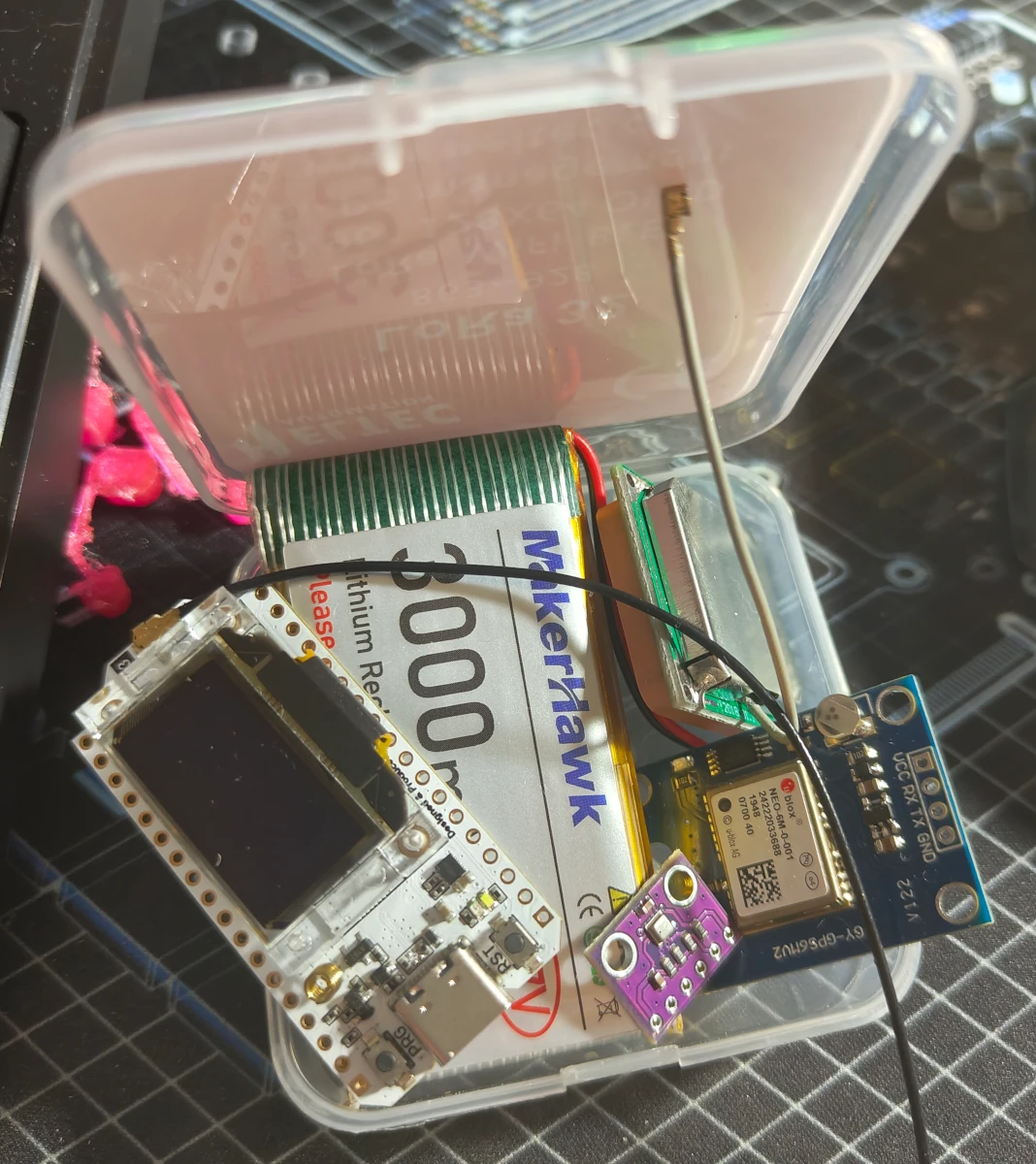
One suggestion was to use the plastic shipping case the parts arrived in, which is a cool idea but it couldn't hold even the battery, let alone all the extra modules I opted to install.
So I searched for a suitable case on Thingiverse and found a number of well made designs, including one with support for a switch, battery, and sensor and a really nice one for a 1A battery.
Unfortunately I opted to go with a giant 3A battery which none of the other cases seemed to support. To this realization, I opted to instead fabricate my own case, (afterall what's the point of having custom fabrication tools if you never use them).
Parts List
- Heltec ESP32 LoRa Base
- 3Ah Li-Po Battery
- GY-NEO6MV2 3.3v GPS Module
- GY-BME280 3.3v Temperature/Humidity/Pressure Sensor
- M2.5 Heat-Set Threaded Inserts
- M2.5-0.45 Screws
- 0.5mm Clear Plastic Sheets
- 2N7000 Mosfet N-Channel Transistor
- Clear Silicone Tube
- 2-Position SPDT Slide Switch
- 28 AWG Wire Spool
I opted to go with these specific modules because both operate on 3.3v so they can be ran with the Li-Po battery. Other modules require 5v to operate so would have only ran via USB power or with a step-up converter.
Electrical
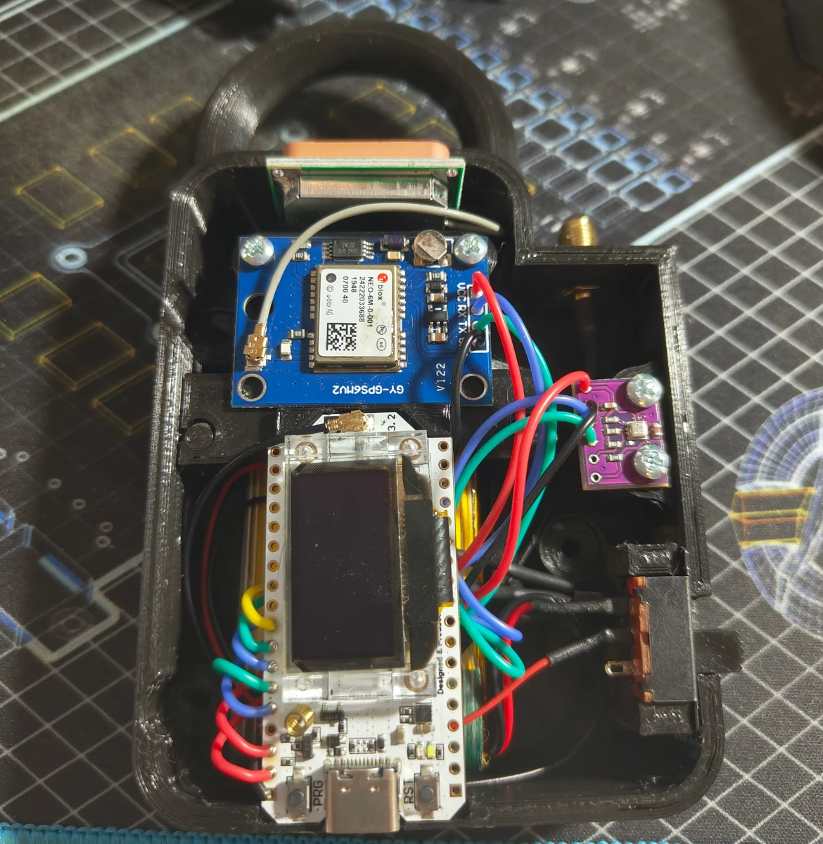
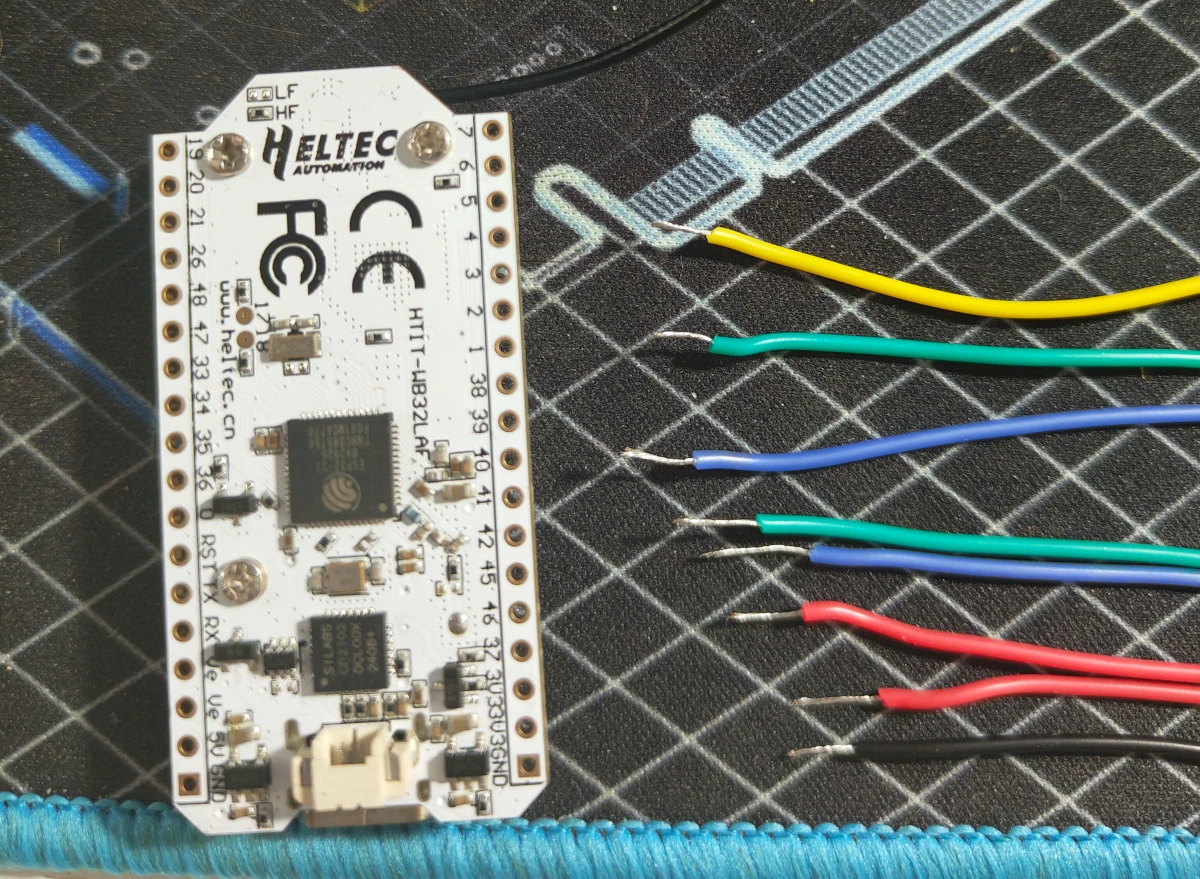
The electrical work is relatively straight forward, and allows for soldering wires on either the front, (my personal preference), or underside of the various modules. Wiring can be done with 28 AWG stranded wire, and color-coded wires should be used to assist with installation and future work.
GND (black wire) is ran to the source of the 2N7000 mosfet and to the GND pin of the sensor module.
One 3v (red wire) is ran to VCC of the sensor module and the other to VCC on the GPS module. The Heltec base module has 2 3.3v lines, so it's easy for 2 modules.
The data pin order is less important as they are all programmable GPIO, but if you change the order, ensure to update the numbering in the application later. For this document, I will use the ordering which I used.
GPIO40 (yellow wire) is ran to the gate on the 2N7000 to enable ground on the GPS sensor; this is done to conserve power by shutting off that module when not in use. (It's generally not good to switch the ground and this really should be on the VCC line instead, but I was too lazy to figure out how to do it correctly and just following the Meshtastic guide. If you are knowledgeable with electrical design and know how to switch this to control VCC instead, please let me know!)
GPIO41 (green wire) is ran to SDA on the sensor module for the data line.
GPIO42 (blue wire) is ran to SCL on the sensor module for the clock line.
GPIO45 (green wire) is ran to TX on the GPS mdoule to receive positioning data.
GPIO46 (blue wire) is ran to RX on the GPS module to send control data.
Drain on the 2N7000 (black wire) loops to the GPS module GND.
Remember, flux is your friend when soldering!

Wire the battery positive to the edge post on the switch with another red wire from the center post on the switch running into the battery clip insert to plug into the Heltec module. The negative from the battery can run directly into the clip that plugs into the Heltec module.
Build
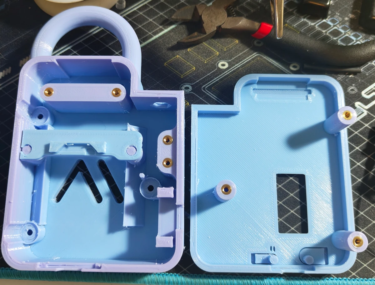
The build is relatively straight forward and includes 3 parts, the back, front, and module support brace. These can be printed at once if your printer is large enough, and no crazy supports are required. (You may need to rotate the front face so the flat edge is at the base of the printer; I exported all the parts in the orientation of the build.)
The source files are included in the downloadable zip and can be opened with FreeCAD.
Depending on the accuracy of your printer, you may need to take a small knife around the buttons to loosen them from the case. Just take care not to completely detach the buttons from the case at the base.
Once printed, the inserts can be installed by just placing them at each point and using a hot soldering iron to gently push them into the slots.
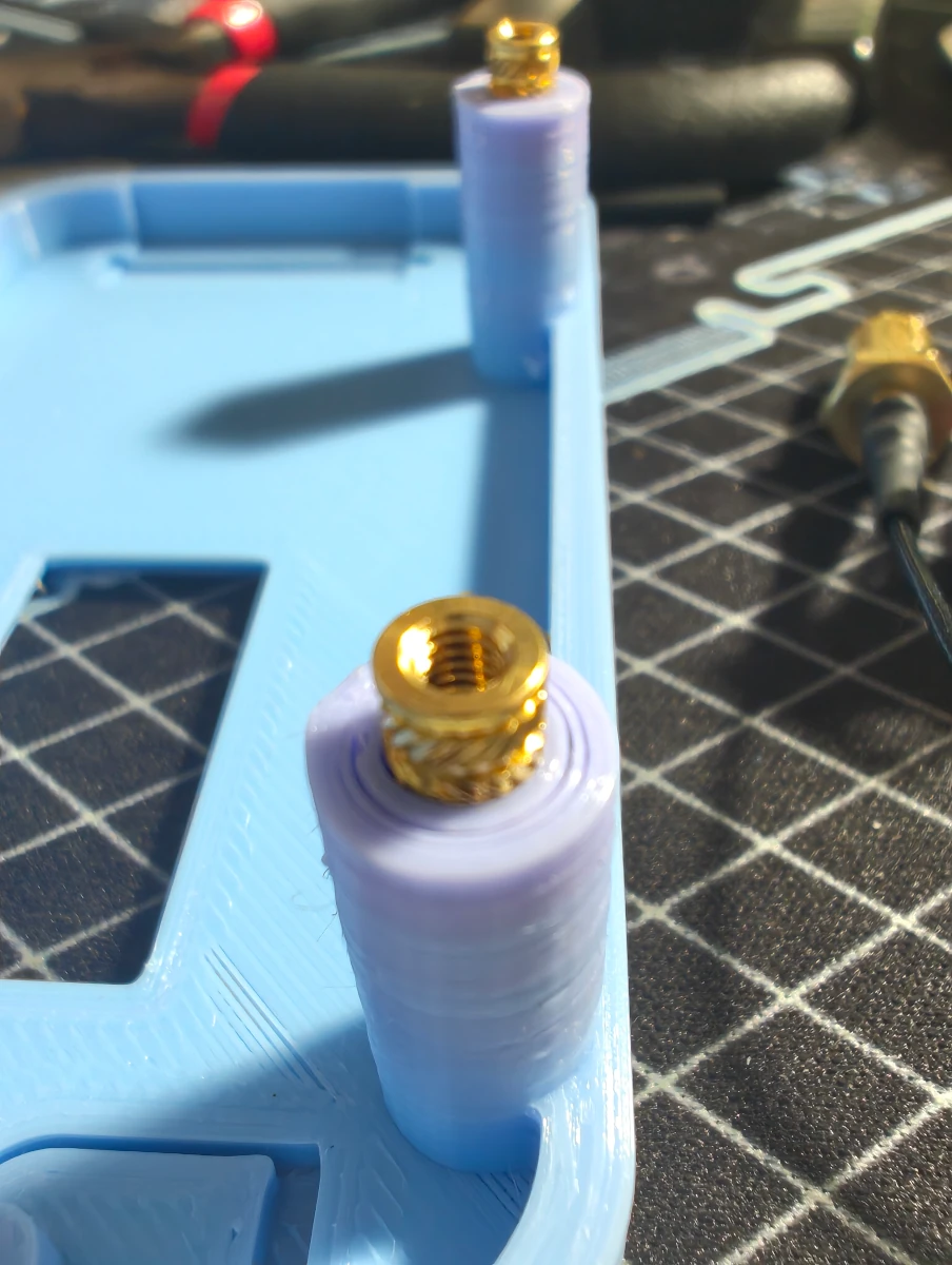
There are a total of 7 insert points; 2 for the GPS module, 2 for the sensor module, and 3 on the front face to connect it with the back.
For extra water protection, the 0.5mm clear plexiglass inserts can be installed along with some silicone epoxy on the back panel and front. This doesn't make the case completely waterproof, but at least will help protect from rain and the occasional splash while attached to your hiking bag.
The GPS antenna rests in the cut-outs integrated into the case to face vertically for the best signal. The GPS module and sensor module are fixed to the back case via M2.5-0.45 screws. Ensure that the module support is snapped into place prior to installing the GPS module, as both it and the base module will rest on it.
The battery can slide under the support brace and the Heltec base module fits snuggly between the brace and bottom of the case.
The switch rests in the switch mount and is held in place by the two faces.
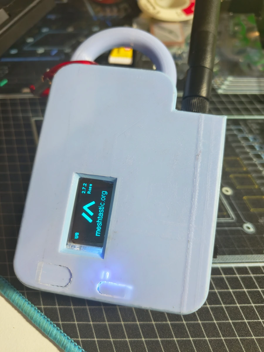
(Ignore the streak on my the image of my print; I need to replace my printer's Wham Bam flexible print bed.)
The large clip at the top of the case allows for easy clipping to a carabiner. The front and back of the case should fit together nicely, (be mindful not to pinch any wires), and everything is held together with the same size M2.5-0.45 screws that hold down the modules.
Configuration
Position
To enable the GPS module, set:
- mode to Enabled
- GPS_RX_PIN to 45
- GPS_TX_PIN to 46
- PIN_GPS_EN to 40
I also recommend setting the GPS update interval to something that makes sense. For devices which will be relatively stationary a update of 86400 (one day) may be adequate, and for hiking 300 (5 minutes) is a decent value. Biking or vehicle nodes may want to have a more frequent check time.
Broadcast interval can also be modified; 900 gives a broadcast frequency of 15 minutes.
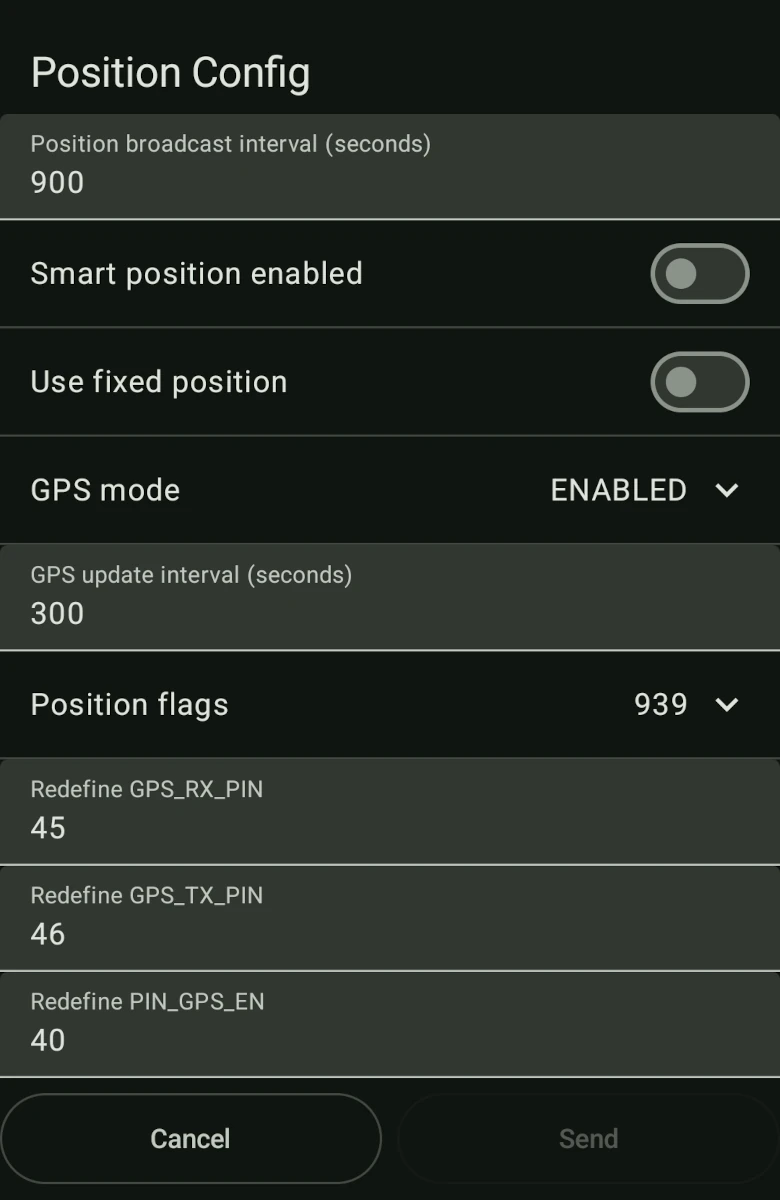
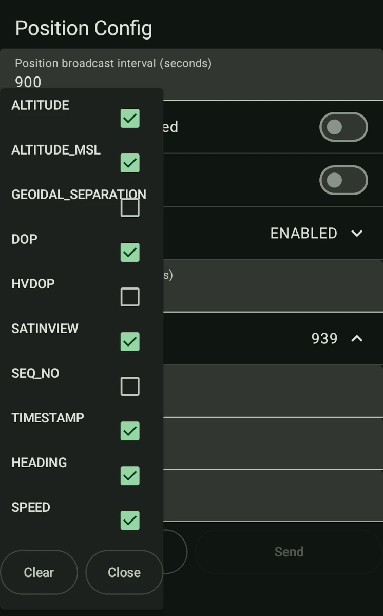
I also add Timestamp to the GPS parameters to update that value to 939. (No idea if this works, but figured might as well since GPS provides an accurate clock too)
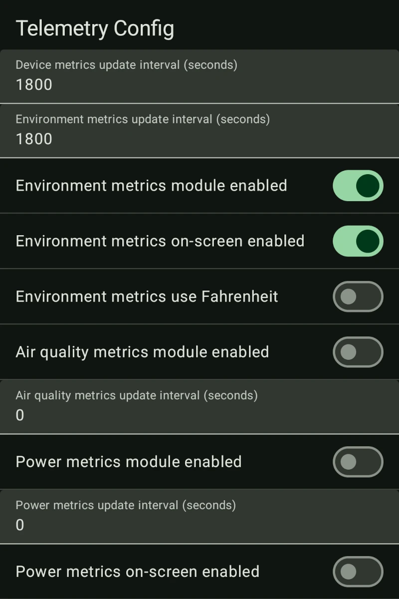
Sensors
For the sensors, just enable the module under Telemetry. I also adjusted the update interval for both the sensors and device metrics to 1800 (30 minutes).
Enabling 'Fake' units, (aka Fahrenheit), will adjust the output on the display, but will not affect broadcast to other nodes.
Timezone
Don't forget to set your device timezone too, otherwise times will be displayed in UTC, which is probably not what you want. This is changed under Device.
Refer to the Posix timezone list for the raw code to enter.
Since I'm in America/New_York, EST5EDT,M3.2.0,M11.1.0 is my timezone. Remember to restart the device to activate this.
Wrap Up
Hopefully this article helps you assemble your own case!